Tel: 0755-83807850
Email: achenwei2000@126.com
Address: Baihua Community, Guangming New District, Shenzhen Dahong Science and Technology Park Building D
 Products Hotline:
Tel: 0755-83807850
Email: achenwei2000@126.com
Address: Baihua Community, Guangming New District, Shenzhen Dahong Science and Technology Park Building D
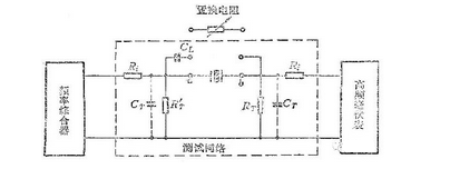
The transmission method measurement line is shown in Figure 1. It is composed of a signal source, a test network and an indicator. In order to ensure a certain measurement accuracy, there are certain requirements for each part of the measurement circuit.

1.Frequency synthesizer (i.e. signal source)
The requirements for the frequency synthesizer are: the output frequency stability is better than 1 × 10⁻⁶ / day; the output impedance must match the quartz resonator; the power output can meet the excitation power specified by the quartz resonator. During the test, the output voltage of the signal source must be less than 10%, the distortion of the sine wave must be less than 15%, and the harmonics should be more than 30dB lower than the fundamental frequency signal.
2.High-frequency millivolt meter (ie indicator)
The requirements for high-frequency millivoltmeters are: high sensitivity and input impedance; stable performance; and wide frequency response.
Test network
The requirements for the test network are: the parasitic reactance XT = 1 / ωCT of the terminals and leads should be much larger than the parallel resistance RT; the parasitic capacitance CAB between the quartz resonator sockets should be much smaller than the static capacitance C0; The parasitic reactance XAB is much larger than the dynamic resistance Ri; the reactance connected to the quartz resonator wire is lower than the static capacitance C0.
In order to ensure the measurement accuracy of the transmission method, the selection of the resistors RT and Ri in the test network should meet the following requirements:
(1) Parallel resistance RT
The resistor RT is connected in series with the quartz resonator. In series resonance, RT is part of the resistance in the series resonance circuit, so when RT is large, it will affect the sharpness of the resonance curve, make the resonance indication insensitive, and increase the measurement error. According to the requirements of the transmission method on the test network, in order to ensure XT≫RT and reduce the impact of CT in the entire measurement frequency range, I hope that RT is smaller. On the other hand, the change in the impedance of the quartz resonator is reflected on the indicator by the voltage on the RT. In order for the indicator to sensitively reflect the change in voltage, a larger RT is required. Taking into account the requirements of these two aspects, it is generally appropriate to select RT = (1 / 31∼ / 10) R1.
(2) Parallel resistance RT´
The resistor RT´ is connected in parallel with the quartz resonator. Its role is to reduce the influence on the input voltage of the signal source. Generally, RT´ = RT is selected. In this way, although the impedance Z of the resonator varies greatly with frequency, the total impedance change of Z in parallel with RT´ is small with frequency, so the input voltage of the resonator can remain unchanged.
(3) Series resistance Ri
The resistor Ri is connected in series between the input terminal and the output terminal. Its role is to reduce the influence of the output impedance of the signal source and the input impedance of the indicator on both ends of the quartz resonator. The choice of Ri should be considered to match the output impedance of the signal source. Generally, it is better to choose Ri≥10RT.
深圳鸿晶宝科技有限公司
SHENZHEN HJB TECHHOLOGY CO.,LTD
地址:深圳光明区白花社区大鸿科技园D栋
电话:0755-83807850/13510762586
传真:0755-83807853/QQ578950488
邮箱:achenwei2000@126.com
官网: www.hjb-hk.com

Copyright ©SHENZHEN HJB TECHHOLOGYCO.,LTD Address: Building D, Dahong Science and Technology Park, Baihua Community, Guangming New District, Shenzhen
Legal statement / sales policy / 粤ICP备2021076367号 电脑版 | 手机版
